 |
<Products Outline> Electric cam controller can synchronize main axis, which is standard axis for movement, with secondary axis and replace from ordinal mechanical cam into electric cam. <Improved points from past model> Event output is the function to output signal by hardware in the specified range against output pulse of ECM-100. |
|
→Example usage of electric cam controller. →Here is introductory video of communication software of electric cam. |
||
| Items | Description | |
|
Control system
|
Microprocessor control system.
This unit carries the high-performance pulse generator,
MPG2032 made by MYCOM.
The exclusive electronic CAM control system made by MYCOM is
used.
|
|
|
Number of axes controlled
|
One axis (Up to 16 axes can be controlled using the daisy
chain connection)
The pulse output systems used are the photocoupler output and
the RS-422 output. Multiple number of units can be connected.
|
|
|
Motors used
|
Stepping motor or pulse train input servo motor
|
|
|
Data store
|
Cam shape, Program and System parameter are stored. (Flash
memory is used. It can be re-written 100,000 times.)
|
|
|
Cam shape
|
32 patterns can be memorized.
The CAM shapes are generated by PC and downloaded.
One CAM shape is composed of maximum 510 plotting
points.
|
|
| Program |
32 programs, 256 steps are stored.
It is possible to store the emergency sequence program which
is executed when an emergency occurs.
Moving command (Electric Cam, Index, Scan, Home search,
Complex trapezoidal drive)
Complementary command (Timer, AND, OR, Arithmetic four rules
calculation, Register, Multi-task, Various setting)
|
|
|
System Parameter
|
Speed mode, S curve acceleration/deceleration, Motor type,
Forward direction, Clock type, Sensor logic, Backlash, Encoder setting, Moving
speed, Memory initialization, Multi purpose output 15 functions setting. Event
output setting, Memory initializing.
|
|
|
Input interface
|
Program start, Cam start, Emergency stop, 16 General purpose
inputs (Photo coupler isolated)
|
|
|
Output interface
|
Ready, Moving, Error, Event output, 16 General purpose outputs
(Photo coupler isolated)
|
|
| Sensor interface |
Forward, Reverse, Near Home, Home, Main axis A/B phase,
Secondary axis A/B phase
(Photo coupler isolated)
|
|
|
Driver interface
|
CW/CCW: Forward direction switchable, Selectable 2 clock or 1
clock, Open collector, RS422
Servo On: On/Off controllable, Photo coupler
isolated
Counter clear: One shot output (about 50ms), Photo coupler
isolated
Alarm: Logic changeable
In-position
|
|
|
Communication
|
RS-232C One channel 9600 baud, data bit 8, stop bit 1, without parity check | |
|
Multiple axes control
|
Connectable up to 16 pieces of this unit with daisy chain
connection. There is a Axis setting switch for multiple axes control
|
|
|
Display
|
Power(Green LED), Error(Red LED)
|
|
|
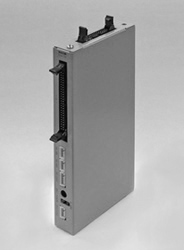
Dimension
|
203(W)×102(H)×25(D)mm (Not including projection)
|
|
|
Weight
|
About 340g
|
|
|
Power input
|
Input
|
Less than 24V, 0.5A for unit Range of voltage;
DC22.8V-DC25.25V
Less than 24V, 0.2A for sensor(Excluding external load)
Range of voltage; DC22.8V-DC25.2V
|
|
Output
|
Less than 5V, 0.2A for encoder Range of voltage;
DC4.75V-DC5.25V
|
|