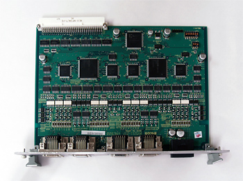


| Features |
| Item | Description | |||
| Control system | Custom LSI MPG2031 command | |||
| VME bus specification | Byte access : Even number Word access: Upper byte |
|||
| Numbers of control axis | 8 axes (Axis name, A, B, C, D, E, F, G, H) | |||
| Applicable motor | Stepping motor and Pulse Input Servo motor | |||
| Basic clock | 3.2768MHz | |||
| Output pulse rate | About 0.1Hz ~ About 1.6384MHz | |||
| Acceleration and Deceleration Rates | About 4.9Hz/sec ~ About 81.9MHz/sec | |||
| Numbers of setting pulse | 1 ~ 16,777,215 pulse | |||
| Pulse output | Output pulse type | 1clk/2clk setting | ||
| CW clock type | Forward/Reverse setting | |||
| Output signal | Open collector | |||
| Logic | Positive logic/Negative logic setting | |||
| Acceleration deceleration type | Proportional shape acceleration deceleration driving/liner acceleration deceleration driving setting | |||
| Functions | PTP positioning, Liner interpolation(2- 8 axes interpolation is available) Home search, Interrupt from encoder signal |
|||
| Driver control output | Contents of signal | Motor free & Counter Reset | ||
| Output circuit | Photo coupler output | |||
| Contents of control | Less than 10mA Dielectric strength | |||
| Driver control input | Contents of signal | Driver alarm, In-position, Logic setting available, General purpose input | ||
| Output circuit | Photo coupler input | |||
| Contents of control | Use maximum 10mA External input power 24V | |||
| Encoder input | Contents of signal | Only Z phase logic setting is available | ||
| Output circuit | RS422 receiver setting | |||
| Contents of control | Maximum 10mA Use external input power 5V(When photocopier uses) | |||
| Sensor input | Contents of signal | Both ends overrun, near home, logic setting available | ||
| Output circuit | Photocoupler input | |||
| Contents of control | Use maximum 10mA External input power 24V | |||
| Interrupt I/F | Interrupt level | IRQ1 -- 6 setting | ||
| Board select | Available access 0xff0000 - 0x0ffffffe by A13-15. | |||
| Power supply | Bus logic power | Less than DC+5V ±5% 1.0A | ||
| Power supply for sensor I/F | Less than DC+24V(external) 0.6A | |||
| Power supply for driver control | Less than DC+5V(external) 0.5A | |||
| Dimension | 233.35×160.0×40.0mm | |||
| Weight | About 400g | |||