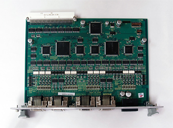


特 徴
■RoHS指令適合品
■独自技術で開発した、1チップ2軸のモータを制御するパルスジェネレータLSI 「MPG2031」 を搭載
■1ボードで最大8軸の制御が可能
■加減速形状は任意形状加減速(S字加減速)・台形駆動
■最大出力パルス1.6MHz
■直線補間駆動が可能
■多軸同期スタート機能
| 項目 Item |
内容 Description |
|||
| 制御方式 Control system |
カスタムLSI MPG2031コマンド指令 Custom LSI MPG2031 command |
|||
| VMEバス仕様 VME bus specification |
バイトアクセス:偶数アドレス ワードアクセス:上位バイト Byte access : Even number Word access: Upper byte |
|||
| 制御軸数 Numbers of control axis |
8軸 (軸名はA、B、C、D、E、F、G、H) 8 axes (Axis name, A, B, C, D, E, F, G, H) |
|||
| 対象モータ Applicable motor |
ステッピングモータ、パルス列入力サーボモータ Stepping motor and Pulse Input Servo motor |
|||
| 基準クロック Basic clock |
3.2768MHz | |||
| 出力パルスレート Output pulse rate |
約0.1Hz〜1.6384MHz | |||
| 加減速傾斜 Acceleration and Deceleration Rates |
約4.9Hz/sec〜約81.9MHz/sec | |||
| 設定パルス数 Numbers of setting pulse |
1〜16,777,215パルス | |||
| パルス出力 Pulse output |
出力パルス形式 Output pulse type |
1クロック/2クロック設定 1clk/2clk setting |
||
| CWクロック方式 CW clock type |
フォワード/リバース設定 Forward/Reverse setting |
|||
| 出力信号 Output signal |
オープンコレクタ Open collector |
|||
| 論理 Logic |
正論理/負論理設定 Positive logic/Negative logic setting |
|||
| 加減速方式 Acceleration deceleration type |
任意形状加減速駆動/直線加減速駆動設定 Proportional shape acceleration deceleration driving/liner acceleration deceleration driving setting |
|||
| 機能 Functions |
PTP位置決め、直線補間位置決め(2〜8軸までの補間が可能)、 原点サーチ、エンコーダ信号からの途中割り込み機能 PTP positioning, Liner interpolation(2- 8 axes interpolation is available) Home search, Interrupt from encoder signal |
|||
| ドライバ制御出力 Driver control output |
信号内容 Contents of signal |
励磁オフ、サーボオン/オフ、リセット Motor free & Counter Reset |
||
| 出力回路 Output circuit |
フォトカプラ出力 Photo coupler output |
|||
| 制御内容 Contents of control |
10mA以下 耐圧35V Less than 10mA Dielectric strength |
|||
| ドライバ制御入力 Driver control input |
信号内容 Contents of signal |
ドライバアラーム、インポジション 論理設定可 汎用入力 Driver alarm, In-position, Logic setting available, General purpose input |
||
| 出力回路 Output circuit |
フォトカプラ入力 Photo coupler input |
|||
| 制御内容 Contents of control |
最大10mA 外部入力電源24V使用 Use maximum 10mA External input power 24V |
|||
| エンコーダ入力 Encoder input |
信号内容 Contents of signal |
A/B/Z相 Z相のみ論理設定可 Only Z phase logic setting is available |
||
| 出力回路 Output circuit |
RS422レシーバ設定 RS422 receiver setting |
|||
| 制御内容 Contents of control |
最大10mA 外部入力電源5V使用(フォトカプラ時) Maximum 10mA Use external input power 5V(When photocopier uses) |
|||
| センサ入力 Sensor input |
信号内容 Contents of signal |
両端オーバーラン、ニア原点 論理設定可 Both ends overrun, near home, logic setting available |
||
| 出力回路 Output circuit |
フォトカプラ入力 Photocoupler input |
|||
| 制御内容 Contents of control |
最大10mA 外部入力電源24V使用 Use maximum 10mA External input power 24V |
|||
| 割り込みI/F Interrupt I/F |
割込レベル Interrupt level |
IRQ1〜6設定 IRQ1 -- 6 setting |
||
| ボードセレクト Board select |
A13〜15で0xff0000〜0x0ffffffeのアクセス可能 0x2000を占有 Available access 0xff0000 - 0x0ffffffe by A13-15. |
|||
| 電源 Power supply |
バスロジック電源 Bus logic power |
DC+5V ±5% 1.0A以下 Less than DC+5V ±5% 1.0A |
||
| センサI/F用電源 Power supply for sensor I/F |
DC+24V (外部) 0.6A以下 Less than DC+24V(external) 0.6A |
|||
| ドライバ制御用電源 Power supply for driver control |
DC+5V (外部) 0.5A以下 Less than DC+5V(external) 0.5A |
|||
| 外形寸法 →外形図 Dimension |
233.35×160.0×40.0mm | |||
| 質量 Weight |
約400g | |||